")
")
")
AMS STANDARD
Application
- medium size airport of category I. and II. according to ICAO
Files for download
pdf Data Sheet (1.55 MB)pdf Certificate MO AČR (580 KB)
pdf Certificate LÚ SR (395 KB)
pdf Certificate SSGA (3.12 MB)
Description/Properties
- well arranged control with use of push-buttons on touch-screen, or by trackball
- well arranged representation of information in several screens on one monitor
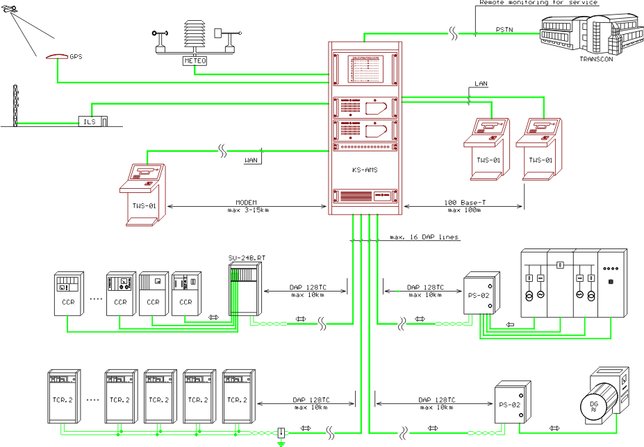
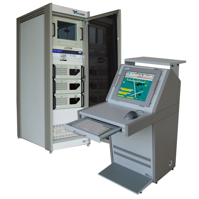
- central unit placed in the rack KS-AMS
- three mutually inter-changeable working sites, which all of them operate as workstations
- communication between working sites with use of the network LAN Ethernet (100 Base-T) up to the distance of 100 m, or with use of WAN modems up to the distance 3-15 km (depending on quality of the line)
- remote control and monitoring of maximum sixteen airfield ground lighting systems in three, five or seven degrees of luminous intensity
- data transfer line for control and monitoring uses only one pair in communication cable
- control and monitoring up to the distance of 10 km
- remote servicing supervision
System possibilities
- control and monitoring of one landing runway (RWY, THR, TDZ, CL)
- control and monitoring of guidance systems
- (ALS) and elevated light (PAPI) from both directions
- control and monitoring of maximum four taxiways (TWY)
- control and monitoring stop bars, extended axis etc. (compatibility with LMS system )
- control and monitoring of flashes
- direct connection to constant current regulators TCR.2 (Transcon)
- connection of regulators made by other manufacturers with use of the rack SU-24B.RT with I/O modules RT-24
- monitoring and control of selected power systems with use of units PS-02 or rack SU-24B.RT
- watching of objects and fire alarm
- connection of meteorological system and representation of its data on the monitor
- automatic setting of luminous intensity depending on runway visual range (RVR)
- time synchronization with use of the GPS system
- monitoring of radio-navigation equipment (ILS, DME, NDB, VOR)
- acoustic signalling of failure states; voice output in language of the user
- archiving of operational and failure states
- in case of utilization of constant current regulators TCR.2 there is a possibility of long-term monitoring of the cables' insulation state of serial circuits with use of well arranged diagrams
- working sites embedded into the tables TWS-01 or stand-alone working sites